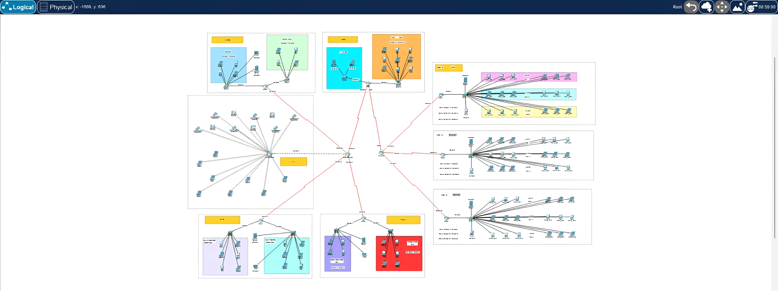
Multi-Floor Call Center Network Design
December 2024Team of 2, led by me
Designed and modeled a multi-tier local area network topology for a four-story enterprise call center accommodating distinct operational and management departments. The scope required segmenting high-density operational teams across Floor 1 (Verifiers), Floor 2 (Customer Sales Representatives), and Floor 3 (CSR) away from Floor 4 (Administration) to eliminate broadcast overhead, enforce strict traffic boundaries, and automate IP addressing across all functional units.
Departmental traffic was isolated using switched VLANs — allocating VLANs 10, 20, and 30 across each operational floor alongside dedicated Floor Manager workstations, and VLANs 40, 41, 42, and 43 for IT, HR/Trainer, QA/QC, and Finance/Compliance offices respectively. Dynamic addressing was handled via dedicated DHCP pools configured directly on the routing layer, while inter-VLAN access control lists (ACLs) were enforced at the router interfaces to block unauthorized lateral movement between operational pods and corporate offices. Dynamic inter-floor routing was established using Routing Information Protocol (RIP), supported by distributed TFTP servers deployed per floor to centralize configuration management and rapid state recovery.
The resulting implementation achieved end-to-end subnet isolation, deterministic routing between floors, and automated endpoint provisioning without cross-departmental security exposure.
Built with
- Cisco Packet Tracer
- VLANs
- DHCP
- ACLs
- RIP routing
- TFTP